Ac To Dc Bridge Rectifier Circuit Diagram
Rectifier circuit bridge working diagram operation theory ac supply 12v circuits transformer electrical types step down use Rectifier bridge components dc circuit ac diagram wave 12v capacitance use make transformer Rectifier bridge diode transformer 220v convert voltage transformers rectifiers structur
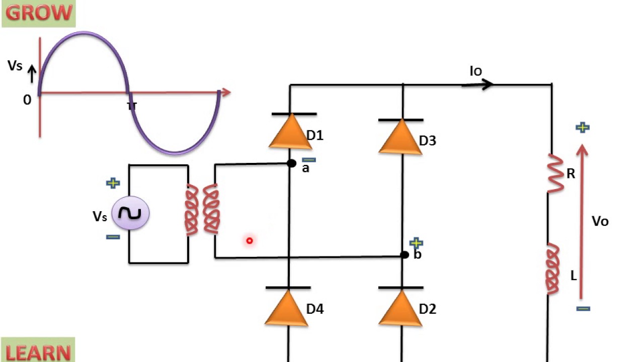
Simple Bridge Rectifier Circuit
Why bridge rectifiers are used in case of dc power supply Rectifiers supply bridge dc case why power used Dc inverter rectifier
Power-supply circuits-ac to dc
Full wave bridge rectifier circuit convert ac voltage to dcRectifier bridge works work does load resistor figure derf step Rectifier circuit bridge diagram wave working detailsRectifier wave circuit voltage capacitor ac dc rectification 12v simple rectified value diode adding working why rectifying do cap stack.
Rectifier circuit power bridge dc ac articles schematic allaboutcircuits supply disassembling schematic2 diodes diode raphaelite push el84 pull linear convertersPower supply Full wave bridge rectifier circuitRectifier diode circuit rl.

Bridge dc power rectifier rectifiers supply case why used stack
Why bridge rectifiers are used in case of dc power supplyAc/dc bridge rectifier and dc/dc inverter circuit Bridge rectifier : circuit diagram, types, working & its applicationsAc-dc converters.
Why bridge rectifiers are used in case of dc power supplySimple bridge rectifier circuit Bridge dc why power rectifiers supply circuit case used usingRectifier circuits.

Circuit rectifier supply power bridge circuits dc ac seekic ic shown below
Rectifier circuit bridge simple diagram ac transformer tapped providing voltage using centerSchematic rectifiers supply bridge dc case why power used circuitlab created using How a bridge rectifier worksDiode bridge (simple ac to dc converter) – my pitcher overfloweth.
Why bridge rectifiers are used in case of dc power supplySimple bridge rectifier circuit Bridge diode rectifier explanation converterWhat components to use to make ac to dc full bridge rectifier with.

Three phase full wave bridge rectifier circuit diagram
.
.


